
by Mark Langford
I was asked at the KR Gathering to provide a little history for the "new airfoil". We've been accused of keeping a great secret to ourselves, the Internet crowd of KR builders and flyers named "KRNet".
I originally became interested in a better airfoil in 1994 while still in the boat stage on my KR2S. I was also helping Larry French design the Lionheart prototype (see http://www.griffon-aerospace.com ), a modern day composite Staggerwing. I created solid models of the entire aircraft and its mechanical systems, from which I drew up plug and end-user construction templates and CAD drawings for most of the hardware as well. While working with Larry, I got a good feel for the aircraft design process, and started thinking about doing a stability analysis on the KR2S, a plane famous for its pitch sensitivity.
I started looking for design data for the RAF48 airfoil, and found precious little. There appeared to be only one scant page of info, which I've put on the web at http://www.n56ml.com/kraf48.html. I called Stu Robinson to see what he could provide, and he laughed that they had never had any design info on that airfoil at the time that they built the KR1, borrowing heavily from the Taylor Monoplane, including its RAF48 airfoil. This is the point where I ditched the RAF48.
At about the same time, I struck up an email conversation with an aerodynamicist who frequented the internet newsgroup rec.aviation,homebuilt. He volunteered to take the RAF48 and feed it into the "Eppler code", a computer program designed to extract Cl/Cd info from a set of airfoil coordinates. His report was that "the experimental data differs greatly from the theoretical results". It seems the Eppler code didn't match the Cl/Cd data in the chart, and he didn't quite know what to make of it. His comment was that the wind tunnels of the era (1920's) were pretty bad, and that he trusted the Eppler code more. He recommended that I should find an airfoil for which more accurate numbers existed, and pointed me to a new airfoil named the NLF(1)0115.
Although the NLF(1)0115 was designed for aircraft flying at higher Reynolds numbers than the KR, at least I had data for it, and I was planning on going pretty fast myself. I talked Larry into feeding the data into his extensive stability analysis program, and out popped a wing incidence and tail incidence, along with expected cruise and stall speeds, among other things. Armed with these, I set about building my wing spars.
During this same time, several of us KR builders had been corresponding by email via AOL's KR forum, which is pretty much defunct now that there's KRNet.
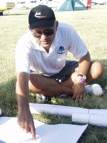
Steve Eberhart
I had finished my wing tanks and was singing the praises of my new lower drag wing, when Steve Eberhart decided to do a little design work of his own. He asked why I was using an airfoil that wasn't a perfect fit for the plane, and why didn't I get the guys who designed the NLF to do one specifically for the KR2S. I told him "knock yourself out", and although I wasn't exactly holding my breath, I DID hold off on any more wing construction for a while just in case.
Since he lives near the University of Illinois at Urbana-Champagne (UIUC) Steve set up an appointment with Dr. Michael Selig, designer of the NLF, and many more laminar flow airfoils and the man reponsible for the very extensive UIUC airfoil site with it's vast airfoil database. Dr. Selig advised that while the NLF(1)0115 would work just fine on the KR2S, he really would like to test a model of it in the wind tunnel to make sure that the calculated data matched reality. He was particularly concerned about the effects of bug guts and rain on lift at stall speed. While the University of Illinois has it's own wind tunnel, it stays booked for nearly a year in advance doing research on airfoil aerodynamics for NASA Glenn Research Center, AeroVironment, Ford Motorsports, Farr Yacht Design and others. KRNetters had cooperatively financed a few other minor projects, and Steve thought maybe there were enough of us that would chip in to finance the wind tunnel project.
That night, I sent out the call to KRNet for contributions toward the wind tunnel fees, and in 24 hours we had $1100 pledged! Dr. Selig said that would do just fine, and Steve set about making an NLF(1)0115 wind tunnel model. KRNet's John Roffey machined the special 4130 spars required for the test specimen, and other contributions paid for the carbon fiber, epoxy, and other materials for the test specimen construction. Sweat and hard labor was provided by Steve Eberhart. Just about the time the tunnel specimen was finished, Steve dropped back in for a visit. It seems Dr. Selig had a doctoral candidate specializing in airfoil design who was looking for a fun project involving general aviation aircraft, and designing an airfoil especially for the KR2S would be just perfect!
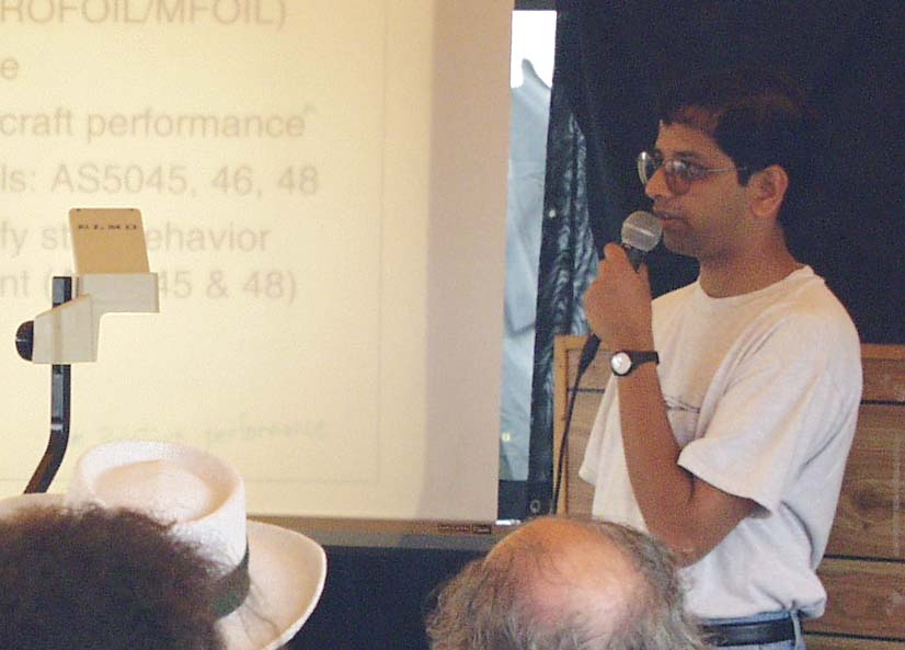
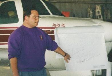
Dr. Ashok Gopalarathnam
explains the new KR2S airfoils at EAA forum at Oshkosh
The graduate student was Ashok Gopalarathnam, currently Assistant Professor in Aerospace Engineering at the North Carolina State University, and whose 1998 summer job at Scaled Composites included designing the airfoils for Burt Rutan's new Boomerang II. Steve knew things were going well when Ashok appeared wearing an EAA T-shirt. With guidance from Dr. Selig, Ashok first designed a 15% "AS5045" airfoil for the KR2S, using a typical cruise speed of 180 MPH and weight of 850 pounds. In the airfoil designation, the A stands for Ashok and the S for Selig. The preliminary iterations for this airfoil (the GA19980222A) were displayed on the web, along with comparisons of efficiency and speed improvements over the RAF48 and NLF(1)0115 used in the same KR2S application. They are not trivial, and the proof is graphically displayed in excruciating detail at the "design" link at the bottom of this page, which includes airfoil refinements and actual wind tunnel results.
Figure A
Figure A compares the predicted performance for the RAF48 and the AS5045
airfoils using Mark Drela's XFOIL code from http://raphael.mit.edu/xfoil. An
aircraft performance program was used to compute the effects of the changes to
the airfoil on the KR-2 rate of climb. The results, shown in Fig. B, demonstrate
the improvement in the high-speed end of the aircraft performance, with a
predicted 10-mph increase in the top speed. Note that these performance
estimates are not intended to be accurate estimates of the absolute performance,
but were used in the airfoil design stage only to provide estimates for the
change in the aircraft performance due to the new airfoil.
Figure B

Dr. Richard Mole
Dr. Richard Mole, (Britain's version of Tony Bingelis) also participating in the KRNet dialog, asked, "since the Cd of Ashok's airfoils is so low, it would be worth trying for a thicker 18% airfoil to get the low drag advantages but also because the increment in CLmax due to flaps is also an increasing function of airfoil thickness, and the spars could be made lighter and stronger?" Presto, an 18% AS5048 appeared! As an avid CAD user, I promptly superimposed the 15% onto the stock spars, and determined that we needed a 16% for a truly perfect fit over the stock "plans-built" spars. A few days later we had the 16% AS5046, with almost identical characteristics!
Mark Lougheed
Mark Lougheed of Seattle, a boat designer and mathematician, fed the new airfoil coordinates and characteristics into a highly massaged CFD (computational fluid dynamics) program, attached to a 3D CAD model of a KR2S. The results of his analysis, in conjunction with his stability analysis, pegged the wing and horizontal stabilizer incidences required for maximum efficiency and stability, and resulted in some truly spectacular images like the one at the top of this page (the AS5046 approaching stall at a 16 degree angle of attack).
Of course, we would really need a wind tunnel test to verify the computer predictions, so maybe we shouldn't waste our precious tunnel time on the NLF, but should test the AS5045 and AS5048 sections instead. Since our tunnel time was quickly approaching, Steve quickly ordered up another set of spars from John Roffey, and cannibalized the NLF specimen for its specially machined 4130 spars.
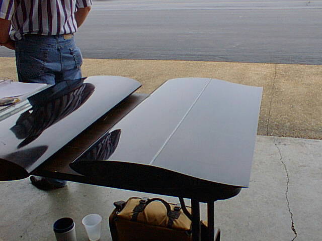
Steve Eberhart's wind tunnel test specimens
After a lot of long days and midnight oil the AS5045 specimen was complete. This thing would bring a concours body man to tears. It was absolutely perfect, and in beautiful carbon fiber black. The picture above can't do them justice. You've gotta see them to believe them. Off to the tunnel with the two specimens, where results were as predicted by the analysis. A new airfoil was born! All we needed was a test pilot...

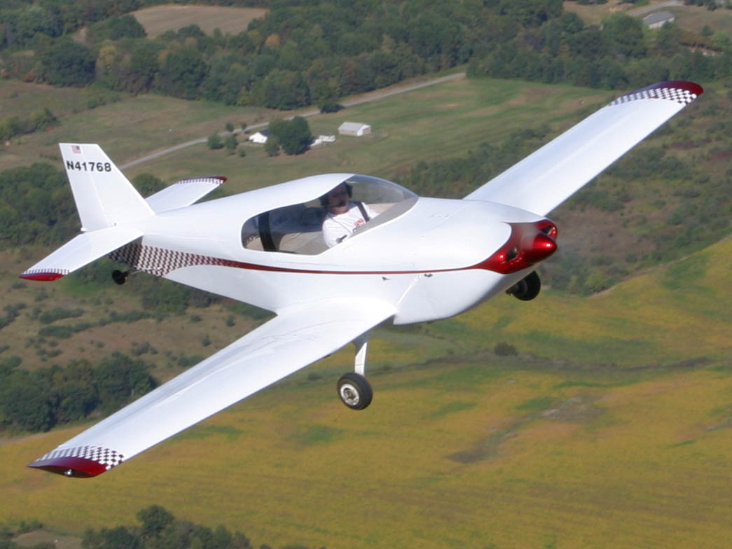
Troy Petteway
Columbia, Tennessee's Troy Petteway had recently damaged his wings (among other things) during a forced highway (well, farm road) landing, and was building new wings anyway. "Higher speed" was all this Sun Race winner needed to hear, and he was installing the AS5046 on his stock sparred KR2. Troy is not only a daily corporate Citation Encore pilot, but A&P and CFI, owning and flying just about every "fun" classic plane you can think of. First flight with the new wing was in July of 99. He reported that even without wheel pants installed, his plane climbed out at a much higher speed, and cruise speed was definitely improved. His plane was also "much more stable" than it had been with the stock wing with exactly the same CG, although most of that improvement no doubt came from increasing the horizontal stabilizer length 4" per side, while reducing elevator area. These improvements came with no penalty, as stall speed remained the same as before, with power off stall coming at 48 knots. The stall was gentle with no tendency to drop a wing. The increased climbout speed (100 mph rather than the previous 80 mph) not only means getting to a safe altitude quicker, but increased engine cooling at the time it needs it most, full power.
One other benefit to the new wing that Troy found, and that no one had really noticed on paper, is that the airfoil actually has slightly more drag than the RAF48 at high wing incidences, such as landing and takeoff. This may not sound like an advantage, but when the KR is a few feet off the runway in ground effect, this increased drag is a welcome brake to shorten the floating process. During takeoff, it increases the run slightly, but takeoff run for a KR is always 2 or 3 times shorter than landing distance anyway, so it helps to equalize the takeoff and landing distances.
Although Troy's plane is both more stable and faster than before, it's still not optimal. The tail incidence should probably be reduced slightly, and he has yet to get his wheel pants back on, so it can only get better!
As of Jan 2001, he has over 100 test hours in, and was still quite happy with the new airfoil. He had unintentionally flown it in a moderate rain shower, and noticed no difference in flying qualities. Ashok, the airfoil's designer was keynote speaker at the "new airfoil" forum at the 1999 KR Gathering, and explained how the laminar airfoil had been tested with "trip strips" in the wind tunnel to simulate the effect of rain and bug guts on the leading edge. Test results matched the theoretical calculations, and there was very little effect.
Troy has recently installed a stock C-85 engine in his plane, which allows a top speed of over 200 mph straight and level. He is convinced that the new airfoil performs better than the RAF48 it replaced in all respects, including fuel economy, due to decreased drag at high speeds.
If your plane is already built, it doesn't make sense to tear the wings off and replace them with the new airfoil, unless of course, your wings need to be torn off anyway! But if you're still in the boat stage or haven't started actual wing construction, now would be the time to consider the new airfoil. The planform and construction methods for the new wing are exactly the same as the plans call for, only the airfoil template shapes are different. You don't even need any new plans, just the coordinates for the new airfoil or better yet, KR2S airfoil templates. The biggest construction difference is that the aft spar needs to be raised with respect to the fuselage to lower the wing incidence. This is partly due to the different airfoil shape, and party to "fix" the fuselage to fly level at cruise speed, rather than nose down like the stock KRs fly when operated at the higher speeds that they are now capable of..
There are three different ways to use the new airfoil. For new construction, the best is probably using the 18% AS5048 at the root, tapering to the 15% AS5045 at the tip. This uses a main spar that is 8.19" tall at the root, making it 17% stronger than the stock spar. It also adds almost 20% to the capacity of the wing tanks. The materials required are exactly the same as the plans call for, except the vertical spacers between the caps are slightly longer. If your spars are already built, the 16% AS5046 is almost a perfect match, requiring only a lamination of 1/8" of spruce to the upper main spar cap to bring it up to proper dimension.
One other change that should be made is the horizontal stabilizer incidence should be reduced to about -.75 degrees, according to Mark Lougheed's calculations. I'll tell you for sure after my plane flies, since it has an adjustable horizontal stabilizer so I can "nail" that number. It will obviously work at zero, since that's what Troy's is still set to, but that's probably not absolutely optimal.
Update, 2012...After many hours of flying N56ML, the trim indicator was off by two LED bars "up", so I shimmed the horizontal stab a total of -1.5 degrees (nose down) and that made the tail incidence almost perfect. Keep in mind that my plane is likely different from yours, and certainly the planform is a tad different, but either -.75 or -1.5 is very close to perfect.

Dean Selby's KR2S - one of the first to fly with the new airfoil.
Update, October 2016 At present, Almost all KR2Ss built or being built use one of the "new airfoil" variations. It's simply a no-brainer to use it, since it's more efficient than the RAF48, which means quicker climb, longer glides, higher speeds, and less fuel burned. Plenty of these are flying, none with any weird stall characteristics or other nasty traits. It's simply a better airfoil. nvAero is now making wing skins for at least one variation so if you're in a big hurry, you can simply buy them. Most of us cheapskates will make our own. Personally, I've built my own wing skins for the AS5046 airfoil, mainly because my spars were already built to stock dimensions. You can see them on my "Outboard Wings" construction page at http://www.n56ml.com/. They are about the same weight as plans-built wings, but the skins are stronger and stiffer, even though I'm using much larger flaps.
To clarify the three airfoil choices, they differ mostly by the "thickness ratio", the maximum thickness of the airfoil section, divided by the chord length. The last digit of these airfoils is either a 5, a 6, or an 8. These digits stand for 15%, 16%, or 18%. So the 16% AS5046 airfoil has its max thickness as 16% of the 48" root chord, or 7.68" thick. It is a good fit with the standard "plans-built" KR2 or KR2S spars. The AS5045 didn't fit the stock KR spars without shaving them thinner, so that one is essentially not used on a KR, except at the tip on a tapered wing. The AS5048/AS5045 is an example of that, yielding more fuel tank capacity at the root and a lower drag, thinner tip.
This airfoil owes its origins to the synergy of KRNet, and several folks working for a common goal. Were it not for the Internet, it would have never happened. And they say there's nothing on the web but smut!
The AS504x Airfoil Design Process
Free KR2S Airfoil Template Downlaod
http://www.krnet.org/as504x/as5046inst.html
