AS5046 and AS5048/45 Installation Instructions
Installation of these airfoils is the same as if you were using the RAF48 templates supplied with your KR builder's manual. These profiles have two sets of lines, one offset by .030", so that if you
accidentally remove some of the outer line, you have the inner one to guide you toward a smooth transition. You can gradually correct the mistake using the inner "backup" line as a guide. All planform dimensions (like ailerons) are the same. The only big difference is that the aft spar is installed about an inch above the lower longeron, rather than directly on top of it. Use a solid block of 5/8" spruce above the lower longeron and between the verticals to obtain the proper spacing.
Ideally, the horizontal stabilizer incidence should be set at -.75 degrees of incidence (nose down) which is easily done by leveling the two h/s spars, and then shimming under the rear spar with a piece of 3/32" or 2.5mm plywood. I'm using the AS5046 on my plane, and although I've made my h/s adjustable (see http://www.n56ml.com/kmlht17.jpg), it's initially set to -.75 degrees as a starting point. (Note that this system is untested, so far).
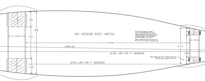
If your horizontal stabilizer is already epoxied in place at the zero degrees incidence called for in the plans, you can install your wings with 1.75 degrees of incidence at the root. The goal is to have 1.75 degrees of "decalage" (angular difference) between the h/s incidence and wing root incidence. The spruce spacer (under the aft spar) will probably be about 1" tall if your h/s is set to 0 degrees, or 1.29" if your h/s is set to -.75 degrees, but these are only approximate. This is ONLY if your h/s is already set to 0 degrees. The templates that we ship are in matched sets, with one version yielding -.75 degrees for the h/s and 1 degree for the wing root, and the other version using 0 degrees for the h/s and 1.75 degrees for the wing root. Use of our h/s and v/s airfoils is optional.
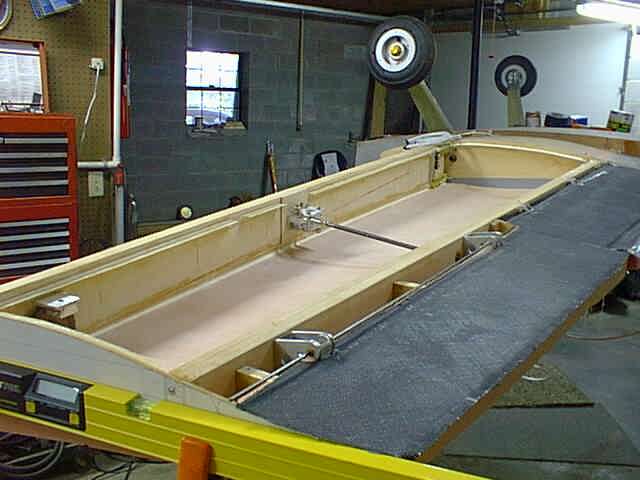
The correct way to set the wing incidence is to level the fuselage (preferably with a 2' level on the upper longeron centered between main and aft spar locations) with the main spar level and glued in place. Glue the templates to your rib plywood (aircraft grade 3/32" or 2.5mm) using spray glue. Cut out the templates using a bandsaw or jigsaw, but cut around the spars leaving the "humps" in place, so that the templates can be slid over the spars. Then glue two of the 48" templates onto the main spar about an inch from the fuselage ensuring that the "LEVEL LINE" is actually level. This will guarantee you a 1 degree root incidence. Slide the aft spar thru the aft spar cutout in the template, thruough the fuselage cutouts, and through the template on the other side. Your aft spar should be in exactly the right place now. Glue the aft spar in place into the fuselage, using the previously mentioned spruce spacers cut to the exact dimension of the gaps they are filling. After the spars have been securely epoxied into place, sand the "humps" off of the templates, and you're ready to either build wing tanks or fill with foam and glass. The rest of the wing construction is done exactly like the KR plans.
One problem that you will encounter with this new airfoil is that the aileron bellcrank, which didn't really fit into the RAF48 airfoil either, definitely doesn't fit into the more tapered aft end of the AS5046 airfoil. There are several solutions. I just moved my aileron bellcrank to the aft side of the main spar, and extended the pushrod. (See http://www.n56ml.com/99062754.jpg).
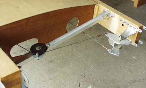
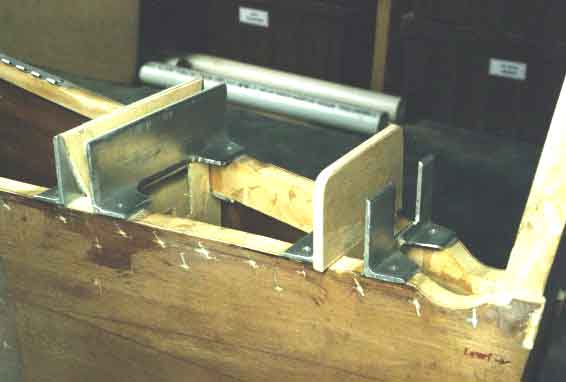
You can also easily move the bellcrank to the front side of the aft spar (along with all of it's
pulleys), as shown here on Mark Jones' KR2S, but this limits wing tank volume, if you plan to build them in the stub wings. Others have flipped the bellcrank upside down and otherwise tweaked it to get it to fit the RAF48 properly, so I don't think it's a big deal to make it fit inside the AS5046 either. As for the AS5048, the stock bellcrank will easily fit inside the wing skin envelope.
The only big difference when building the AS5048/15 is that it would be nice if you
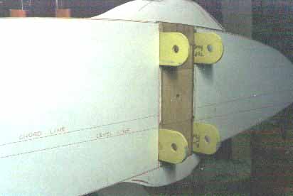
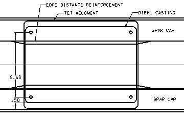
laminated spruce reinforcements to the bottom of the top spar cap, and to the top of the bottom spar cap where the Diehl gear attach brackets bolts to gain a little more bearing area on the spar caps. The gear brackets are about 6.5 inches tall, and the spar is 8.2, so you only have an inch of bearing on top and bottom. That's probably enough, but you might want to add a little more spruce. Just in case you don't have your gear yet, it is supposed to be mounted as close as possible to the fuselage.
While on the subject, make sure you don't epoxy your gear legs to the brackets until AFTER you sand the airfoil foam to contour. Otherwise the leg interferes with a large area of the stub wing's cross section and prevents
achievement of the proper contour. Don't ask me how I know.
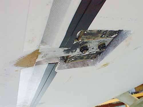
One thing we've learned about the AS504x airfoil series is that it's pretty sensitive to that huge gap that's created under the leading edge of the aileron. Climb is dramatically improved if that gap is sealed with mylar gaps seals as shown above on Troy Petteway's KR2. The photo shows the area around the aileron counterweight. The material to use is .010" thick Mylar film, which can be bought at Rideout Plastics at http://www.ecomplastics.com from Ridout Plastics, Inc., 5535 Ruffin Road, San Diego, CA 92123 (phone 858- 560-1551).
The stuff is clear mylar film, and their part
number is MYLCLR.010. It's described as 0.010"x24"x48" clear mylar, and cost $6.15 for that sheet. Anywhere else you can buy it from would be just fine too. You need a pretty strong double sided tape to secure it and I'd recommend 3M No. 444 that can be bought from Grainger (among many other places), item number 1F227, at $7.94 a roll.
Probably the best solution though is to build the aileron like the plans using
piano hinges, except round the lower edge which then "nests" up into a cavity formed by extending the lower wing's skin far enough to act as a gap seal.
Return to AS504x Airfoil Site.