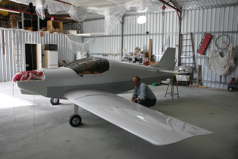
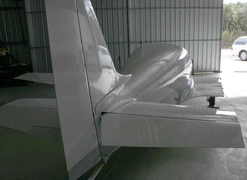
Wayne Bone's KR2S
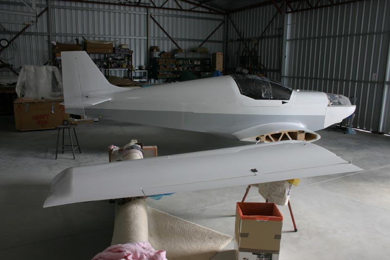
Wayne Bone's Australian KR2S
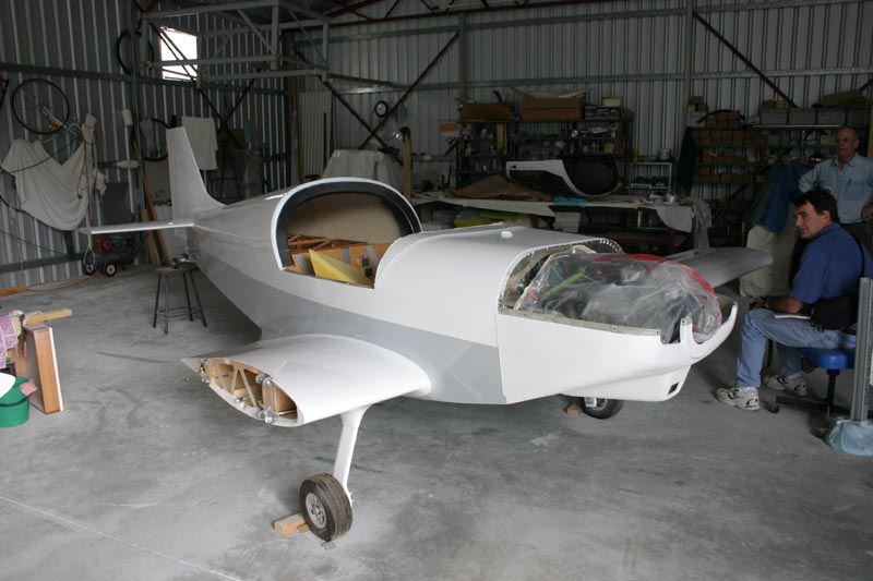
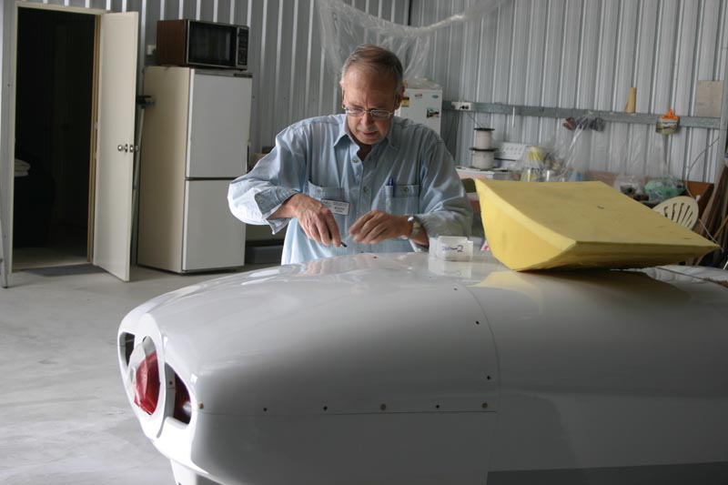
Lower cowl and a red dividing stripe are yet to be added to complete the paint job.
Airfoil: 18% - 15% as per Mark's templates.
Outer wing panels each carry F/G tanks of 36 litre capacity located in the inner two
bays behind the spar. These tanks only extend half way back to the rear spar.
The fuel cap can be seen on the header tank, that has a volume of 30 litres, which
is only 150 mm. from front to back (to minimize C.G. variation during burn off.)
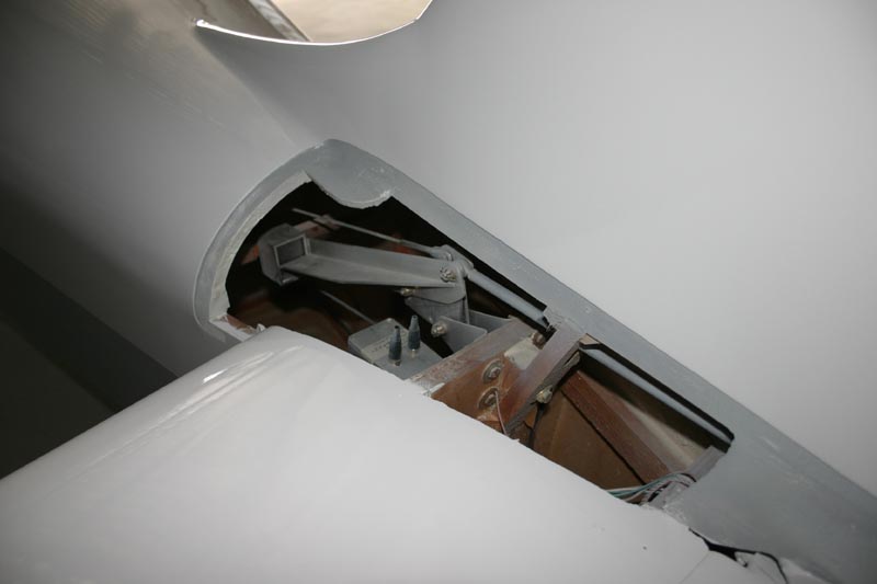
Elevator counter balance can be seen here. Elevator control is via push rod under
the seats to a bell crank. Cables then connect to a bell crank in front of the Hor. Stab. forward spar.
A push rod then connects to the elev. horn. Bearings are used throughout.
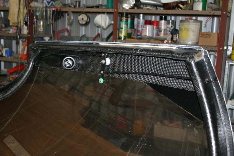
Canopy lower edge. Two plus layers of carbon fibre / epoxy resin, are used around
the edge of the canopy both inside and out. The forward and rear bows have lay ups
over a balsa core. An eyeball vent appears in the top. Top centre, the rod locking
mechanism is shown.
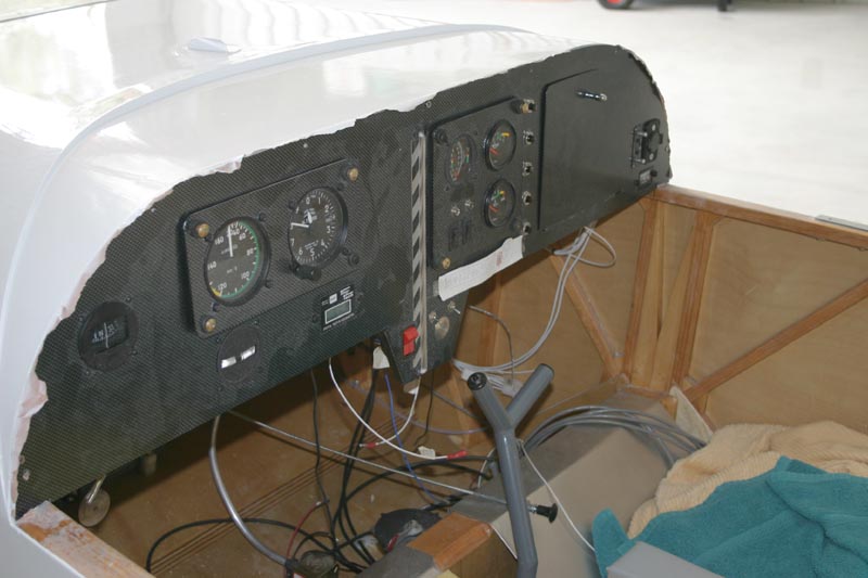
Very basic VFR with sight gage indicator for the fuel level of the header tank only.
Wing tanks pump to the header. Aluminium sling seats are screwed to the spars.
Portable radio and GPS will mount near the sight tube. Taco. will be replaced.
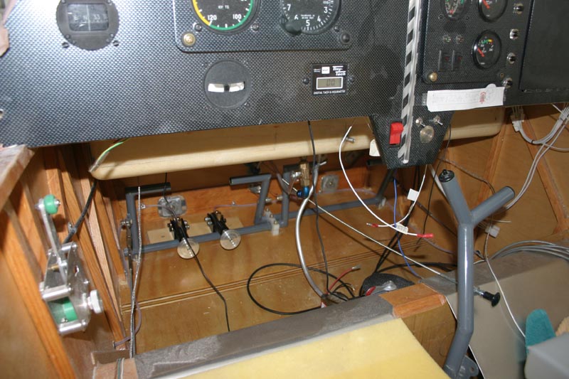
The fuel tank is evident below the instrument panel.
Behind the heal brakes the aluminium plates are glued with captured nuts to support
the lower engine mount bolts. The choke cable will be mounted on front of the control stick through a bracket mounted on the spar cap. Both choke and carbi. heat are mounted here. The control stick mechanism is a copy of Chris Hinze "Zenith Zodiac" setup (my previous project).
Cowl is fixed with camlocs. Piano hinge is used to hold the lower half to the fuselage.
Wheels are AZUSA with Tracy O'Brien's compact disc brakes… www.tracyobrien.com
Hot air box bolts to the front of the carbi.
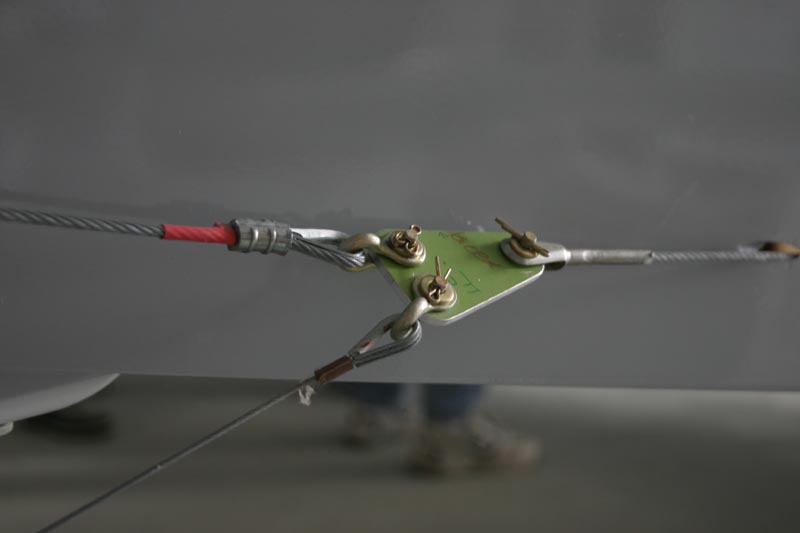
Rudder / tailwheel cable junction
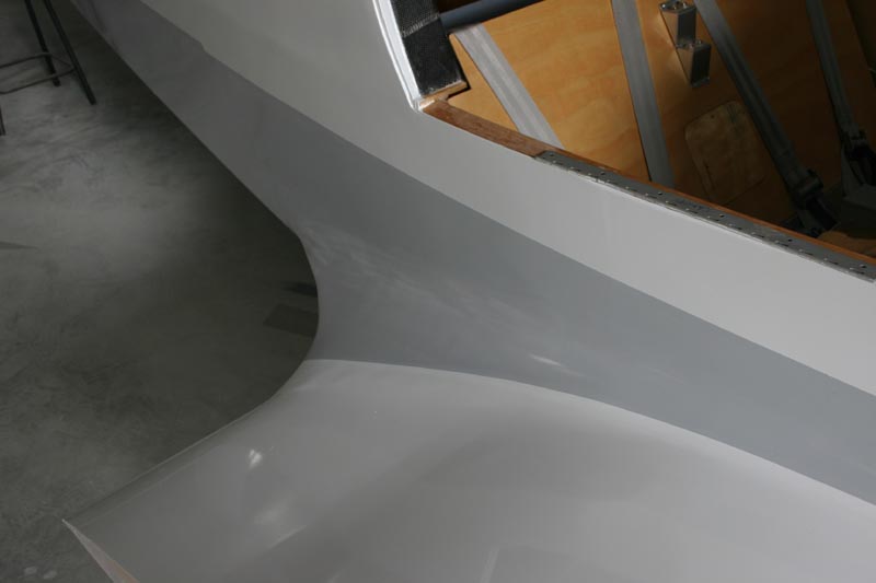
This fat fillet is the big advantage in F/G construction.
Intercom sockets are just visible at top right.
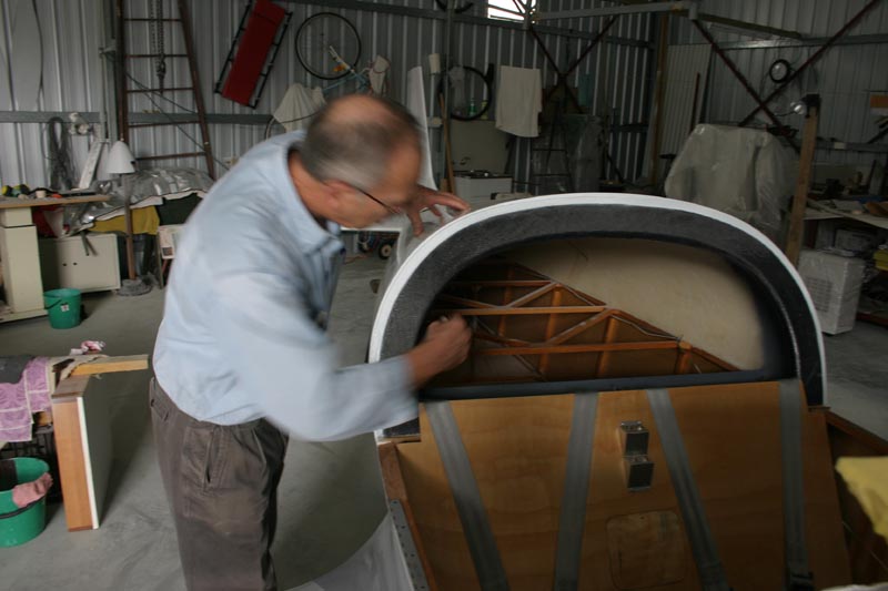
The rollover bow has three layers of carbon fibre over a balsa former. The turtle deck is glassed on the inside as well.
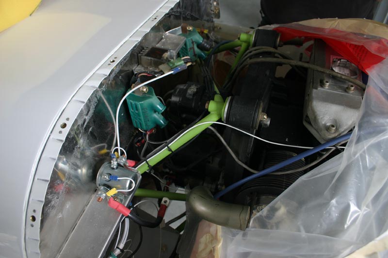
Power is by a local VW conversion "Aeropower" with one mag. and an electronic
ignition.
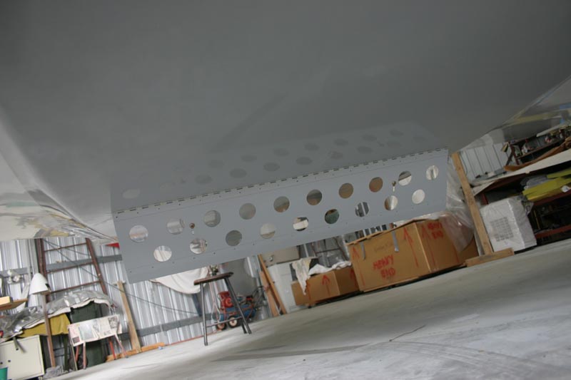
This Air Brake is hinged in front of the rear spar. A handle activates it from the pilots
left hand in two stages… sixty degrees and eighty degrees. When retracted the belly
has a smooth finish as mushrooms fill the brake holes.
A commercial tail wheel is fixed to F/G spring of cross section 40 x 13mm. It's is to be seen if this size is heavy enough.
The tail access panel fits flush when screwed in to position. The elevator / hor.stab.
gap worked out very small with the rodend/eye bolt hinge.
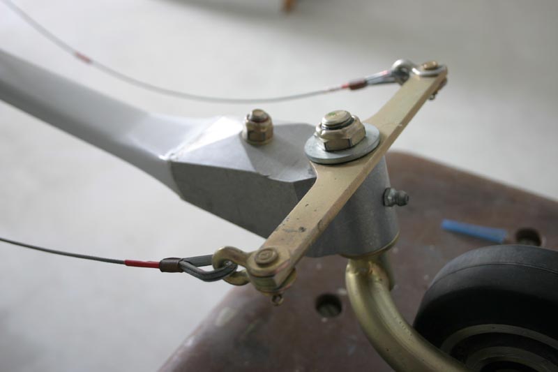
The aluminium block supporting the tail wheel has been filed down to streamline its appearance.
A little more counter wt. is being added to the aileron. There is an eye bolt protruding above the lower wing surface half way along the main spar cap. This will be used with a small shackle looped through a tie down cord. My spars timber extends right to the foam tip. It's very evident here that this KR-2s has been stretched… As per Mark's thoughts, I stretched the rear fuselage a further 14" and extended the F/W forward a further 1.75". Have not done the weight and balance yet. The canopy was blown here in Perth out of 1/8" sheet. The fuel cap at the front of the canopy is as far forward as I could locate it in the tank.
the outer tip of the Aileron bellcrank can be seen here bolted to the Aileron pushrod. Only pushrods are used to activate the Ailerons.
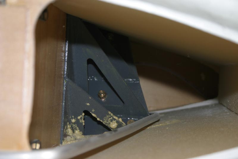
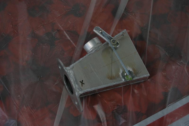
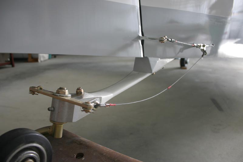
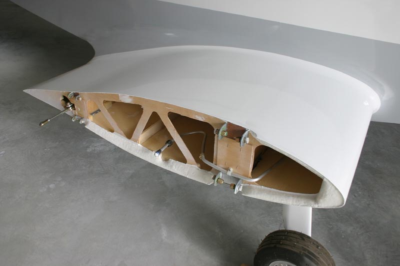
The main undercarriage bracket is welded up from 4130. It was laser cut, welded, then finally heat treated. The size was made to suit my deeper 18 % spars. Two bolts can be seen that fasten the F/G leg onto the far side of the bracket. The legs were laid up on a former to a thickness of 22 x 100mm. wide then pressed to squeeze out excess resin. About 80 layers unidirectional glass were used for each leg. The L.E. was rounded and the T.E. was tapered with a drinking straw stuck to the rear edge ( to take brake line). Two layers of bidirectional matt at 45 deg. bound the whole package overlapping on the edges. The tail wheel spring followed the same construction method to smaller dimensions. The aluminium tube from the centre of the pic. to the bottom LH corner is the fuel line that connects from the wing tank via a Facet pump to the header tank.