KR Aluminum Tank Construction Technique
Dana Overall
1999 & 2000 National KR Gathering Host
After starting construction of my RV-7, after selling my KR-2, I concluded an aluminum fuel tank for the KR would be doable
with the new metal working skills I had learned with the building of my RV. The tank I built for my KR was a foam tank with
vinyl ester resin. With prior tank construction experience in both aluminum and fiberglass, I hoped a comparison of building
techniques would be beneficial for the KR community. The wings tanks shown in this document are outboard wing tanks for
Mark Jones. The airfoil used by Mark is the new airfoil. I am not going to post measurements, as each tank for a KR would
probably be different. I am going to document the techniques I used along with a material list. Builders with measurements to
suit their needs can use these techniques.
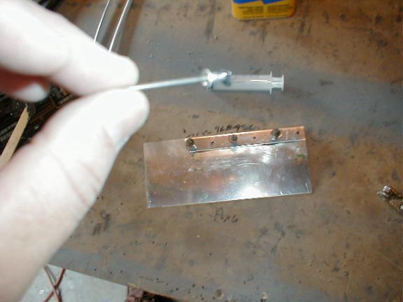
This picture pretty much shows all necessary tools to accomplish a successfully constructed aluminum fuel tank.
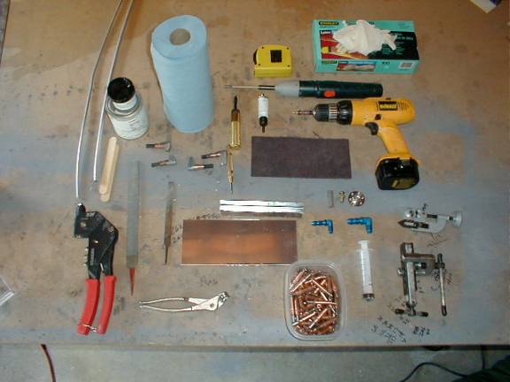
From left to right, bottom to top are the following: variable head hand squeezer, vixen file, metal file, cleco hand tool, .032 2024 alclad T3 aluminum, 1/8” clecos, AN833-4D vent line bulkhead fitting (with this you will need a AN924-4D nut, AN818-4D nut and
an AN819-4D sleeve), AN833-6D fuel line pickup bulkhead elbow (with this you will need a AN924-6D nut, AN818-6D nut
and an AN819-6D sleeve), 3/8” fuel screen, CAV-110 drain valve, VA-112 drain flange, 35 mL (cc) veterinary syringe, 37
degree flaring tool, pipe cutter, ¼” aluminum vent line, 3/8” fuel pickup aluminum line, tongue depressors, cleco clamps, drill
punch, scotch pad, 1/8” drill, AD-42-H solid pop rivets (one per inch), proseal fuel tank sealant, towels, two deburring tools, 1”
hole saw drill bit, tape measure and gloves. Throw in some acetone and 6 AN-32-H pop rivets for the drain valve flange and
you are in business.
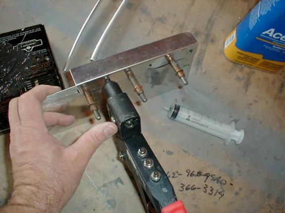
I’ll start off with some basic aluminum construction techniques and then apply these to the actual tank construction. These
pictures will simulate the riveting of the tank floor to the front tank wall bottom flange. I bent the one-inch flange into the front,
back and both side walls so the tank floor would be supported on all four sides. First lay the tank bottom on the one-inch flange
and drill through the bottom and flange at the same time. Drill into your workbench and place a cleco through the tank bottom,
flange and into the bench. Drill holes one inch apart and cleco as you go to maintain hole alignment.
Take the parts apart and deburr all holes. In addition use your vixen file to smooth all straight edges and your metal file to
radius all corners. Additionally, use your scotch pad to scuff the gloss finish off all parts that will prosealed and clean with
acetone, otherwise the proseal will not have a good surface to bond.
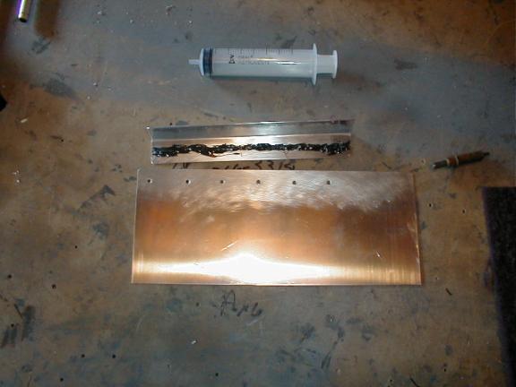
Using the syringe, lay a bead of proseal on the tank wall flange cheating towards the wall of the tank. Place a cleco in every
other hole.
Dab the AD-42-H pop rivet head in the proseal and insert in every other hole. Keep plenty of shop towels handy
and use as many gloves as you need. Keep your tools clean. These rivets are solid rivets that do not leave a hole in the shop
head side after you have pulled the nail. They cost .05 per rivet but they are worth the extra cost to assure a leak free tank.
Now just rivet every other hole, then remove the clecos and finish riveting. In that most KR builders will not have enough clecos
to rivet every other hole in the entire tank, cleco the tank together on all four corner with a couple in the middle to hold alignment.
Use your remaining clecos in every other hole in the line of your riveting. When you pass a cleco, just remove it and
place it at the end of line.
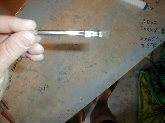
After you are finished with the rivets, it is time to seal the tank for good. Take a flux brush and cut the bristles down to about ½
of original length. This will give you a nice stiff brush to force the proseal into tight spots and up against the rivet heads.
Take that brush and proseal over each rivet head and form a fillet at the floor and wall joint.
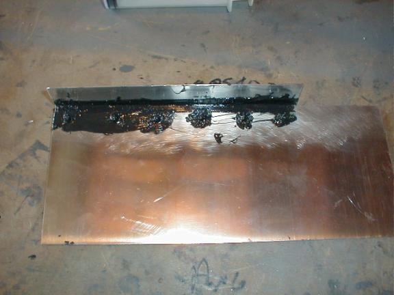
After I’ve dabbed each rivet, I like to go back and join all the proseal edge lines together. I feel this gives you less line surface
area for leaks to occur.
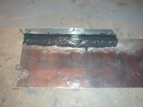
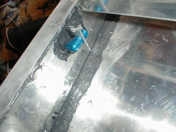
You will notice in the above picture, my scuff area extends past the proseal width. No fuel will now get under the proseal and
out the rivet holes.
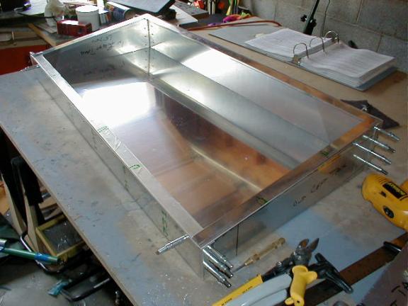
The material used in the tank construction is .032 2024 alclad T3 aluminum. I used a hydraulic break to put the bends in the
aluminum. A hand break can be used, just make sure the radius is adjusted properly so as not to make a very sharp bend. The sharper the bend, the more at risk you are for stress cracks from induced weakness of the material at the bend. First I drew the
various parts out on the flat stock and added one inch to the bottoms of all sides. These I broke to make the one inch flange
for the tank bottom to rest. In addition, I added an inch per side on the front and back wall and broke those inward. These
are my flanges to rivet the sidewalls to the front and back walls. These can be seen in following picture.
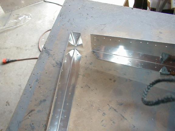
Now, how did I get those angles cut into the bottom flanges? Overlap the flanges and cut a line through both flanges. This
makes your joint line perfect for these two pieces. Be sure and have the pieces clecoed together on the flanges.
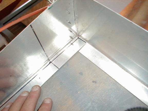
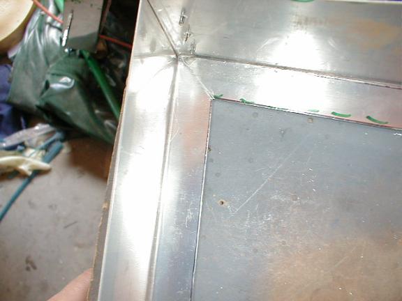
After doing this, lay the bottom in and drill through the bottom, flanges and into your work bench. Cleco as you go, directly into
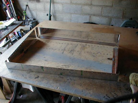
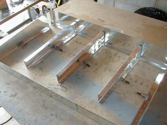
your workbench. You will notice in the following picture a flange around the top of the tank. I used 2” pieces of aluminum,
broke down the middle and riveted to the walls as a resting bed for the tank top. This technique allows you to cheat a little to
make a nice flush surface to rivet the top on when the time come. These flanges also add rigidity to the structure.
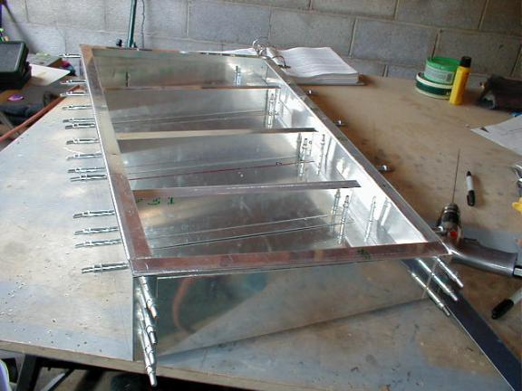
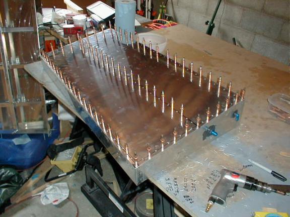
Lay your tanks baffles in and drill these to the front wall and bottom of tank. Remember, cleco as much as you can, this
maintains alignment. In this picture I have not yet drilled the one-inch holes in the front of each baffle. I subsequently drilled
three holes per baffle. I intentionally left the baffles one inch shorter than the width of the tank and one inch shorter than the
height of the tank. This will allow fuel to flow unabated to the fuel pickup but will not adversely affect sloshing of fuel from side
to side. As you can see, the end of each baffle does not have a flange. This will allow fuel to flow for and aft and will not be
a place for water, or other contaminants to get caught.
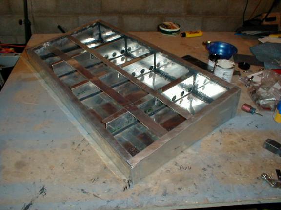
This picture is a good one showing all components of the inside of the tank. The middle support ties the baffles to the top
skin and the bottom skin. The rear strap will keep the aft portion of each baffle from flexing as the fuel moves side to side.
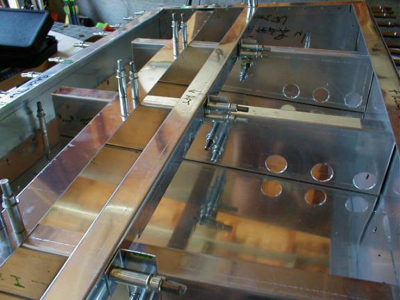
This is a good picture showing the makeup of each component.
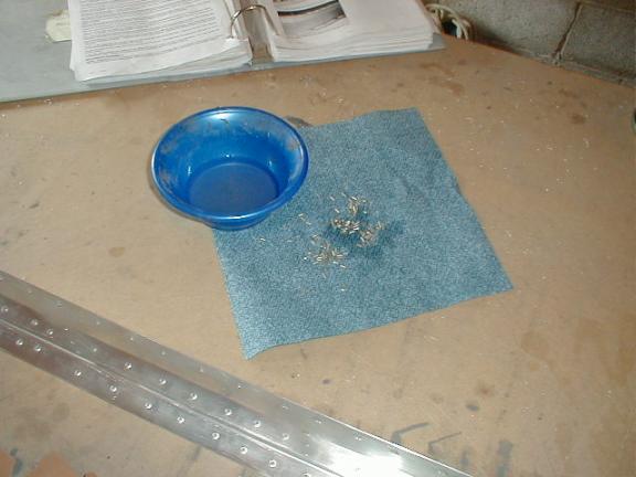
Before you start riveting, soak your rivets in acetone and do not handle them with your hands. You want all the oil off these
things.
One tank, less vent line, fuel pickup line and drain valve. You will notice I have taken the flux brush and made a nice fillet along
all mating surfaces of all parts of the tank. I paid particular attention to the corners of the tank.
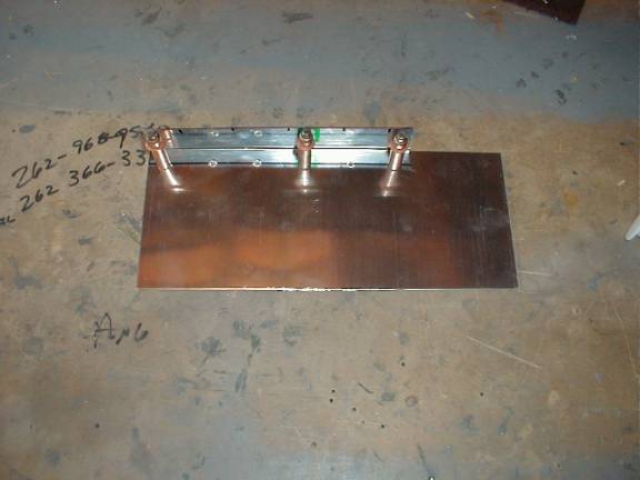
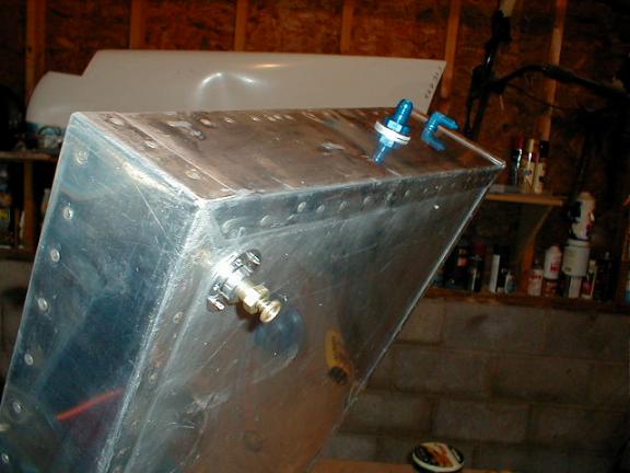
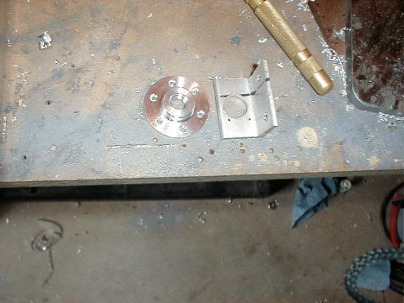
Showing the placement of the vent line, fuel pickup and drain valve. The vent line points directly down. This enables the builder to simply run this line out of the bottom of his wing. The drain valve should be in nice alignment with the one-inch foam of the wing bottom.
Inside the tank, I manufactured an anti rotation bracket for the fuel line pickup. Without this, when you tighten the outside nut
you would have a tendency to rotate the entire elbow. This is nothing more than a 1” X 1” bracket with a 9/16” hole centered
at 5/8” and riveted to the side wall.
Now all you have to do is run a ¼” vent line to the outboard front corner of the tank and install your fuel line pickup tube to
complete the inside of the tank. The top of the tank is drilled and riveted on last. Remember, once again cleco as much as you
can. As you are final constructing the tank, work form the bottom up with the one-inch top flanges being the last pieces you
rivet on to complete the internal construction of the tank. If you are building a tank that is much taller than this tank you may
want to add a couple stiffeners on the tank floor running side to side between the baffles. These would be nothing more than
left over one inch by one inch pieces left over from the top flanges. This would keep your tank bottom from flexing and
possibly loosening up your baffle rivets.
Now, drill your 1/8” holes through the top. Be sure and scuff the mating surfaces up, figure how you want to make a fuel cap
inlet and install a sending unit based on builder preferences. This is a good time to go back and add a little extra
proseal to each bottom corner, just for good measure. Proseal a good bead around the one-inch flanges and rivet the top on.
Be sure you have leak tested the tank prior to this. Leave water in the tank for several days. If you do have a leak around a
rivet, just drill it out and pop another one in with proseal.
If you have any questions, please feel free to contact me off the KRNet at Bo124rs@hotmail.com